
This is why I dont like using 1/4″ routers – the bits snap easily.
Carbide is brittle and I accidentally knocked the spinning bit as I lifted the router out of the hinge mortising jig.
$30 down the drain.
Phil & Dianne's house building diary

This is why I dont like using 1/4″ routers – the bits snap easily.
Carbide is brittle and I accidentally knocked the spinning bit as I lifted the router out of the hinge mortising jig.
$30 down the drain.
It was a hot day today (36 decrees C), and has been quite warm for the last few days. At about 1pm I noticed that the hot water service was boiling.
Normally on a hot day it boils/gurgles a little bit, maybe overflows about half a litre, and that happens throughout the day every 20 mins or so. And thats OK. Thats what its supposed to do – its an open vented system.
Well, today it just continued to boil, like a kettle, non stop. I didnt think that was too good, so the only way I could think to cool it down was to cover the solar evacuated tubes. So I got up on the roof with a canvas tarp, and covered up the tubes. Problem solved.
So, I am thinking that might be a regular occurrence, particularly when we have built the house and are not drawing much water (ie heat energy) from the hot water tank.
Will have to keep an eye on it.
This is a followup to the Fire Protection post, where I contemplated using my petrol generator to power my water pump in a fire emergency, rather than using a separate petrol powered fire pump.
I have tested my generator with the main electric water pump, and it works fine. I turned on the sprinklers, and the fire hose outlets, and the generator was able to drive the pump.
So, this saves us about $900. I actually think its a better solution because both the pump and generator are ‘on demand’, rather than permanently on like a fire pump. With the fire pump, once its on, then you are pumping water, even if you don’t need it right then. With the electric pump, it come’s on when the line pressure drops. And, the generator can run in ‘eco’ mode for about 6-8 hours on one tank of fuel – much better than a fire pump.
My water pump is quite sizable for a domestic pump – its a 2kva pump, and its water output is comparable to the fire pump we would have bought.
So, we will go with that till someone convinces me otherwise.
Today we installed the solar hot water evacuated tubes. The hot water service is already installed, so I have just been waiting till my plumber can come and do the tubes and commission the unit.
The tubes are 1.8m long, and there are 30 of them.
One end goes into a manifold where the water from the tank runs through, and the other end just goes into a plastic mounting boot.
Each tube is like a thermos flask – its a double walled glass cylinder, and between the two glass walls is a near complete vacuum. Inside the cylinder runs a copper tube that has glycol inside it. The tube heats up from the sun, transfers the heat to the copper and thus the glycol. The glycol gets hottest at the top of the copper tube (the bit that goes into the manifold). Water flows through the manifold, and the very hot copper tip transfers the heat to the passing water.
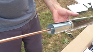
The water circulates from the hot water tank (which in my case is up inside the roof), through the manifold, and back into the tank. The circulation operates by thermosyphon – there is no electric pump required. Cold water is drawn from the tank from an outlet that is low on the tank, the manifold inlet is higher than this tank outlet, the manifold is on a slight incline, and the water returns to the tank on an inlet that is above the height of the top of the manifold.
When installing the tubes into the manifold, heat transfer paste is smeared onto the copper ends so that there is good thermal conductivity between the copper of the tube and the copper of the manifold.
Note: keep the tubes covered when they are sitting in the box ready for installation, else the copper ends will get too hot (from the sun striking the glass) to handle and apply the paste.
The manifold has rubber gaskets to ‘seal’ around the glass tube. These gaskets proved to be a real pain in the arse – we could not slide the tube into the manifold without pushing the gaskets off their seating. So, we ditched the gaskets – they were proving to be of limited value anyway. Probably really only used to stop a bit of moisture/rain from entering the manifold, but I don’t really think that would matter much anyway.
Once all the tubes were installed, and the manifold pipes penetrating the roof were insulated and lagged with tape (to protect the insulation from birds and UV), we could fill the tank and test wait for sunshine to heat things up.
Basically the thermosyphon would work or it wouldn’t. If it didn’t, then the backup was to install a small circulating pump. We may install a pump regardless, because of frost. On a cold night we dont want the manifold water freezing, and bursting pipes, so keeping it circulating every half hour for a few minutes would solve that.
I am starting to think that I might not get a petrol fire pump. I need to see if my Honda 2kVA generator can run the 1.8kW electric house pump. If it can, then we dont need a separate fire pump because the water output from the fire pump is similar to this electric pump. The electric pump would be better too in a fire because if you turn the hose off the pump will stop, unlike the petrol pump. So you wont waste as much water when putting out spot fires or embers.
The only benefit of the fire pump is that it could draw water from the ponds.
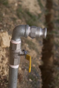
Here are the sprinkler and fire hose points we have set up on the 50mm ring main pipe.
 |
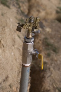 |
There is one sprinkler at each corner of the workshop, one at each corner of the house, and one in the middle of the long sides of the house. There is one fire hose point on either side of the workshop, and one hose point on either side of the house. They are 25mm hose outlets. All the sprinkler heads and hose outlets have their own ball valve on them so they can be opened individually as needed.
The idea of the sprinklers is to wet down the area so embers cant ignite. Much better to have sprinklers near the ground, rather then on the roof tops. If they are on the rooftops, the high winds that occur during a fire will just blow the sprinkler water away and it will be useless. With sprinklers near ground level there is a much better chance that the water will get where you need it – on grass and on walls.
The multiple hose points mean you dont have to drag heavy hoses around the block. You just have sever (4) hoses, one at each point, and use them as needed.
I had to carefully design the width of the windows, as there are a number of components to consider, as mentioned here.
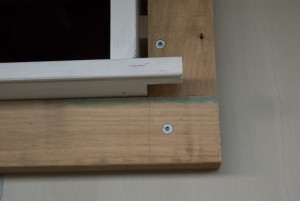
So when it comes time to install a window, I need to put a ‘frame’ of 90x45mm timber around the window so that the weatherboards and window trim abut the window at the correct depth.
(note: need drawing here)
As you can see in this photo, I have installed the 90×45.
 |
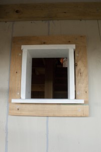 |
I chose to fix the 90×45 into the framing studwork behind the sheeting with 100mm screws, rather than nail it.
38x45mm cement sheet window trim will be fixed to this subframe, directly abutting the window frame, which will leave 45mm for the weatherboard fixing.
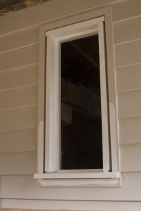
The second window to get built and installed is for the storage room. This window is more or less the same as all the other windows in the house. The difference between this and the window in the garden shed is that the sill has horns.
These horns extend the sill either side of the jams, and are mostly decorative in nature. Because the sill overhangs the weatherboards, the architrave cannot be carried across the bottom if the window. So the architrave must abut the sill, and the horns provide a place for this abutment.
I may choose to put an apron under the sill – I have not decided yet.
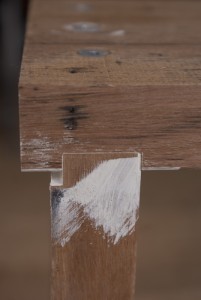
Prior to assemble, where the jams join the head and sill, I have applied two coats of paint to protect the timber.
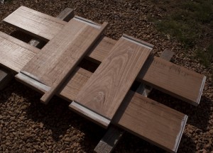
The window is then assembled using three 75mm screws per joint.
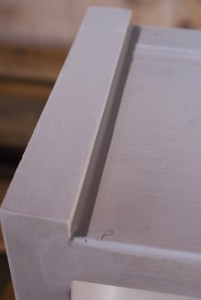
Here is a closeup showing the drip groove cut into the front underside of the sill. This grove is cut with a few passes on the tablesaw, with the blade set very low (about 6mm).
Any holes, checks etc are filled with putty, then the window is painted with three coats of 3-in-1 undercoat/sealer/primer.
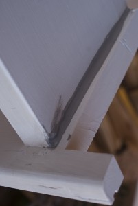
Just prior to installation, the exterior joint intersections are sealed with polyurethane to stop water seeping into the joints.
 |
 |
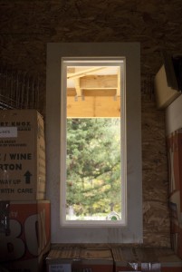
Installing the window is a case of sitting it in place, then shimming the sides to make it plumb. I am fixing the window in place with screws in the jams. I am screwing through the jams into the frame studs. The screws will be hidden bu the glazing/sash mouldings, so I have to take care to put the screws where the moulding wil hide them. The alignment shims are placed at the screw positions, and act to chock the jams where the screws go through so the jams dont get pulled out of shape.
Once the window is in place I put some architrave on the inside. As this is a store room I just used MDF architrave stock that I was given by a neighbour.
 |
 |
The garden shed window is the first window to be assembled, because its the smallest.
The core widow frame is just a sill and head, each with rebates to house the jams.
The head and jams are 221mm wide buy about 33mm thick. The only reason they are that thick is because thats the timber that was delivered to me, even though I asked for 25mm rough sawn. There is no point in making it thinner, other than surface planing to straighten the exposed face.
The jams have to be jointed together, because the timber is 190mm wide. So I need to joint on another 30mm. A real pain. It makes the whole process take so much longer. These joints are not using biscuits – I could not see the point. Also I am using Titebond III PVA glue rather than epoxy, so I can get quicker clamp-up times, and because I will orient this joint to the inside so it will not be exposed to the weather.
I am housing the jams into the rebates so to help eliminate twisting over time.
 |
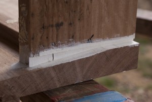 |
All the joints are getting two coats of primer/sealer/undercoat prior to assembly. I then use three 100mm type 17 screws on each joint.
In the case of this window I need to add an apron piece below the sill to match up to some existing brickwork on the shed. The apron was biscuited and glued on.
The whole frame will then get three coats of undercoat both inside and out. The reason for undercoating the outside (ie the bit thats hidden by the window frame) is to stop moisture ingress into the frame. Timber warps less if all sides are coated evenly.
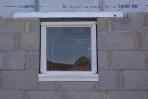 |
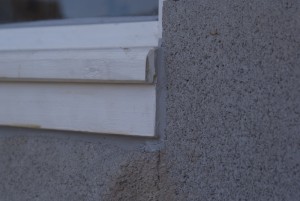 |
The ends of the weatherboards, where they meet the corner/end-cap trim, needs to be sealed with polyurethane prior to painting, for weatherproofing.
This is essential, but a pain to do. Its hard to get it neat on the under edge of the boards, and its a bit tedious. Oh well, you’ve just gor to do it right if you want things to last.
I tried several tools to smooth out the goo, but in the end a finger is the best. All the nail in the trim needs to be punched in and filled also. I am using a exterior filler that is sandable and paintable.
I have finally started making windows, and the sills are the first step. This has been a long time coming, and I have a heap of work ahead of me for the windows. Before we started the house we had decided to make our own windows, because the cost of buying professionally made windows was just way too expensive. It was going to cost us $30,000 for double glazed windows for the workshop, and $39,000 for the house – and that was the cheeper end of the quotes we got. The most expensive was $60,000 just for the workshop!
We want timber windows. Primarily for the aesthetic, but also because of the thermal properties of wood. Whilst PVC windows are probably the best thermally, I do not particularly like them, and am not even sure if we could get BAL-29 rated PVC windows. Not a huge fan of aluminium windows either – they would not suite the look of the house, and we would have to get aluminium clad wooden wooden frames because AL is a terrible insulator. These would prove to be expensive also.
So, timber it is; and we must pick from a list of 7 timber species that have been fire rated and found suitable for BAL-29 and above. We have ended up with Silvertop Ash. Whilst in many cases it looks like Vic Ash, its much heavier.
The window frames need to be 221mm wide to suite the walls we are making. It works out like this:
So the sills need to be 250mm to cater for the horns on weather ends of the sill that the window moulding will sit on, and to provide a weather lip over the weatherboards.
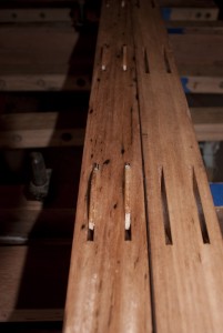
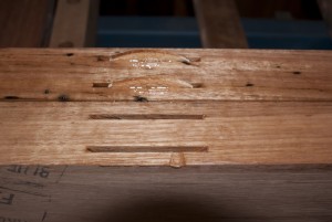
Each sill is made from two pieces of 140 x 45mm stock that is edge jointed together. I am using a router with a straight bit and a 24″ jointer hand plane to do the jointing. Then I put in two rows of biscuits to align them, however in hindsight one row would have been fine. The reason I say this is because when planing the bevel on the sill on some boards I exposed the biscuits because they were too close to the finished surface.
 |
 |
I am using a West Systems epoxy glue for the sills because the join will be exposed to the weather (under paint). I am finding the epoxy easy to work with because it has a relatively long open time when compared to a PVA like Titebond. However the disadvantage is a very long cure time in clamps (8 – 12 hours). With the clamps I have I can only clamp up 2 long sills at a time. Note that epoxy is a gap filling glue, so you do not need to clamp up as tightly as you do for PVA. I brush the epoxy on with a disposable brush.
Once out of the clamps the shaping can begin. I have made up a simple sled for my router that rides on a track consisting of an MDF base and two pine rails.
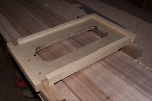 |
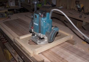 |
I am using a 3 horsepower Makita router, with a surface planing bit. The bit has 3 replacable carbide inserts, so I get 4 cutting edges per insert before I have to replace or sharpen the inserts. This bit and router combination work very well, and I get only very minor ‘tracks’ in the planed surface which can be belt sanded out.
Whilst I have a thicknesser capable of handeling this size timber, its no good to me because neither surface of the glued up plank is perfectly flat. So running it through the thicknesser would only produce a twisted board out the other end.
Therefore I sit the glued up stock on my sled base, and use small timber wedges to shim out any wobble in the board. Then I surface plane one face, flip it over and surface plane the other face. Once the first face is planed true, I could run it through the thicknesser for the other face. However I am already set up with the router so I just continue on with it on the other face.
To put the bevel on the main face, which is about 90mm wide, I use my electric planer to rough it in, then set a chock piece under one edge and again use the sufrace planer in the sled.
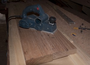 |
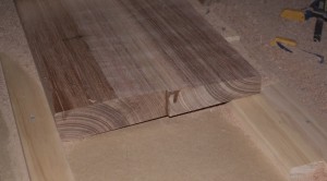 |
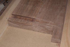
Then I need to cut out the horns at either end, and route a rebate at either end to house the jambs.
 |
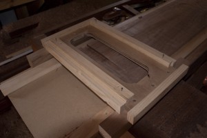 |
The rebates are cut with the router, using a straight cut bit. I again use the sled, clamping it in position on the table. I have fixed side rails to the sled that the router base runs up to, to control the width of the rebate. The rebate is cut only as long as the jambs are wide – 221mm.
I also hand plane a radius on the front edge of the sill, just because I think it looks nicer.
The final step is to cut a drip channe under the front edge using the table saw.
And thats how I make the sills.